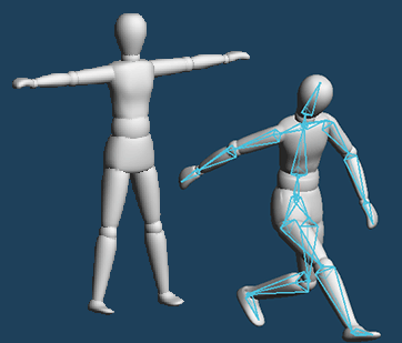
You can make posing model by setting bones.
This tutorial will explain basic of [Bone] command.
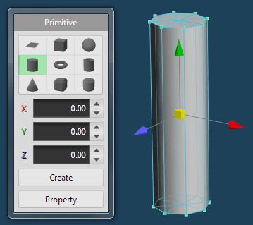
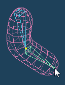
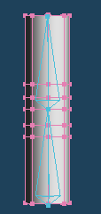
First, make an object for moving by bones.
Make cylinder by [Primitive], and deform slender by [Scale].
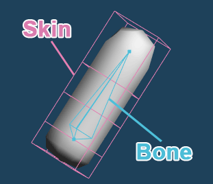
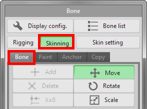
Bones can be added in [Rigging] mode.
The clicked position as the starting point, a bone is created by mouse drag. The point where the mouse button is released make the end point of the bone.
You can connect a new bone to a bone if you create bone with dragging the end point of the bone.
 |
 |
 |
| Drag a mouse | A bone is displayed yellow when a mouse cursor is pointed on it. Drag it and create a new bone. |
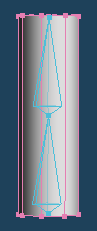
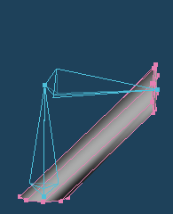
Place two connected bones in the cylinder object as shown on the left.
Associate bones with objects after placing bones.
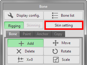
Click [Skin setting] in Bone panel and open the setting window.
Confirm a cylinder object in the list of [Target object] is checked, and press [OK].
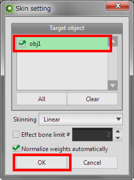
When an object that is not assigned weight is added to target, weight of each bone is automatically assigned to target object.
With this, you can deform objects by operating bone.
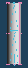
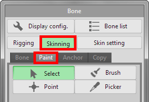
Bones can be operated by [Move], [Rotate], [Scale] in [Skinning] mode.
Click the tip of the upper bone and drag the mouse to move it.
|
|
 |
When you move the bone, vertices moves with the bone.
As shown above, if there is no vertex near the bone's joint, the object doesn't bend along bones.
 |
|
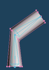 |
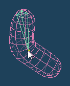
By [Knife > Continual cut], add vertices on joint. This object bends along bones.
 |
|
 |
If you further add a vertex near the joint, the shape of the object is less distorted when bent.
How to distribute weights to vertices will be explained.
This time, we adjust the weight on [Paint] tab of [Skinning].
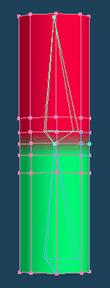
While you select [Paint] tab, distribution of weight is displayed with color coding.
If weight color display is not multiple color, set [Weight display > Multi color] in [Display config.] on the upper left of the panel.
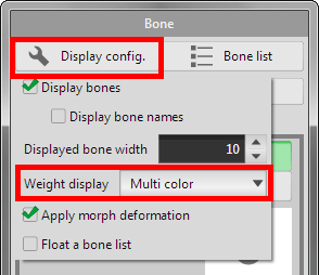
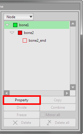
Weight color of each bone can be changed from [Property] at the bottom of [Bone list].
Automatic weight assignment by [Skin setting] do setting minimum required weight distribution.
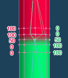
The numbers in the following figure are weight distribution of each bones. The red number is the upper bone, and the green number is the lower bone.
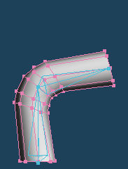
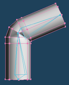
When moving the upper bone, the object is bent as shown below.
The maximum value of weight is 100, and the minimum value is 0. If there is a large difference in the weight value between vertices, the shape of the bent object is distorted.
Change weight assignment by [Point] of [Paint]. Select the bone by [Select] tool and the vertex by [Point]. You can see the weight value of this vertex for the bone.
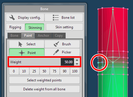
You can change the value of weight by inputting value in this box or pressing the lower numeric button.
Assign weight so that they change step by step as shown below.
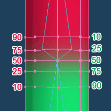
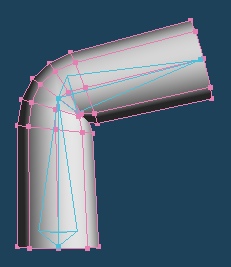
The joint of the object bent more naturally.
See the next tutorial if you want to learn more practical how to use [Bone] command.
And, see the manual if you want to know other functions of [Bone] command.